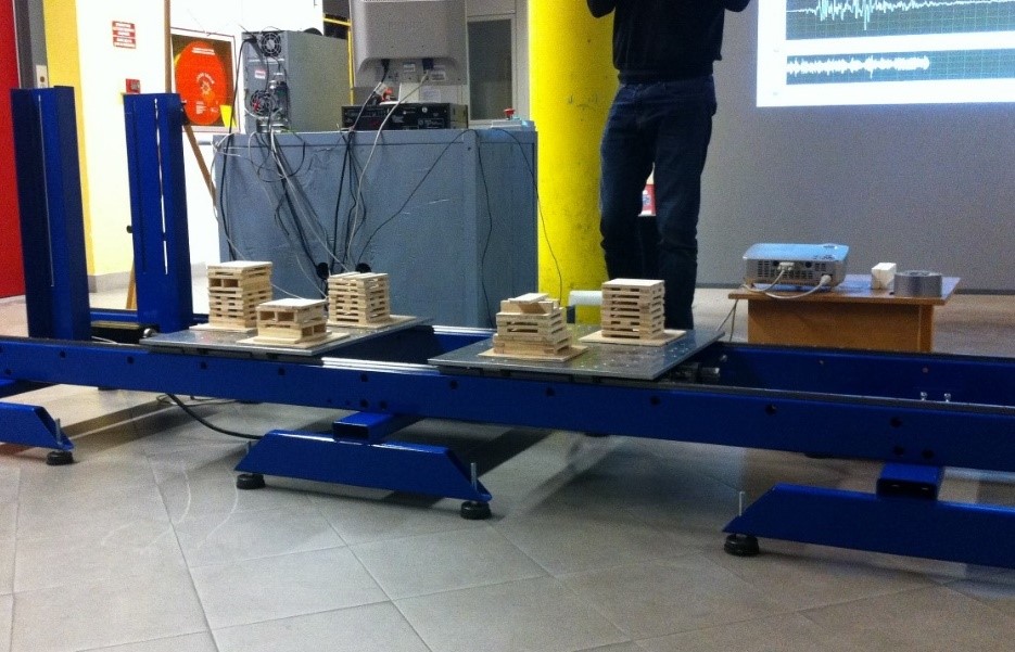
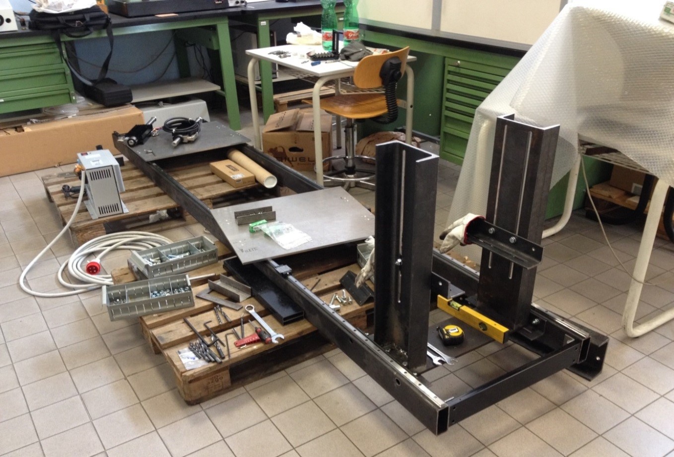
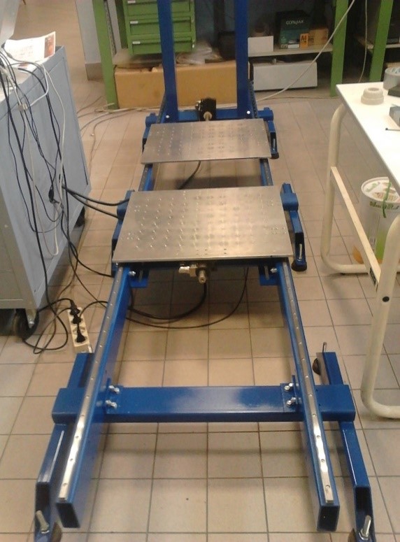
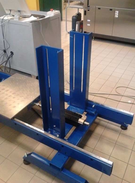
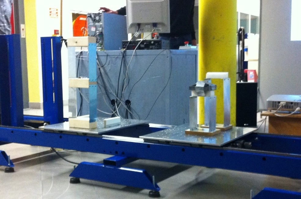
The shaking table is bidirectional and composed of two steel platforms of dimensions 600x500mm moved by two dynamic actuators on linear guides. The main reason of its design is to be able to test scaled bridges models with a small size shaking table by making work the platforms separately which allows to gain distance between them, as well as the platforms can be moved joined depending on the needs of the test performed. The shaking table was designed also to carry out hybrid tests by installing one actuator elevated in the lateral support. The actuators consist in linear electrical engines with a maximum force of 585N, a maximum displacement of 330mm and a maximum velocity of 1700mm/s. The functioning of the control is very easy. From the accelerograms the data input is obtained and these values of accelerations are provided with a frequency. Then, in order to improve the quality of the control, the number of values of acceleration for each second are increased up to 200 values. The electrical engines are controlled by signals of positions, and with the purpose to obtain the equivalent position values, the integration of the acceleration values is needed. Once these values are known, they are passed to a National Instrument analogic/digital converter. As an output, this converter produces a value of tension that it is proportional to a value of displacement. Then, the electrical engines read this value of tension and create a value of displacement. Finally, it is possible to check the real value of acceleration from accelerometers.
In the shaking table visit, simple structural models including a single degree of freedom (SDOF) model, a SDOF with passive seismic control systems and a two-story shear frame were tested. After the study of the structural models, a soil liquefaction test took place, and at the end of the performance, the students were able to participate in the shaking table test by building some structures in a seismic design competition. During the experiments, the main concepts and data outputs were discussed.
The dynamic characteristics of a structure depend on the interaction of the stiffness of the structure with its mass, which is mainly contributed by, e.g., the mass of the floors, structural walls, infill walls, beams, columns, and the mass of the live contents such as furniture and people. The response of a structure during an earthquake is a function of its dynamic properties. Therefore, it is beneficial to demonstrate the effect of the stiffness and mass on the dynamic characteristics and the response of a structure for a fundamental understanding and appreciation of this interaction. The numbers of bays and stories also affect the stiffness and mass and accordingly the dynamic characteristics. Hence, in this firs part of the visit, the main objective was the observation of the resonance behaviour in a model by modifying the dynamic properties of the structures and by implementing passive seismic control systems. The building structure tests were conducted using a sinusoidal sweep. Application of a sweep with incremental frequency is particularly useful for direct observation of resonance as it allows to visualize that only some of the harmonic excitations are dominant. These models were attached to the shaking table, except in the base isolation test, with accelerometers installed to measure floor displacement and accelerations.
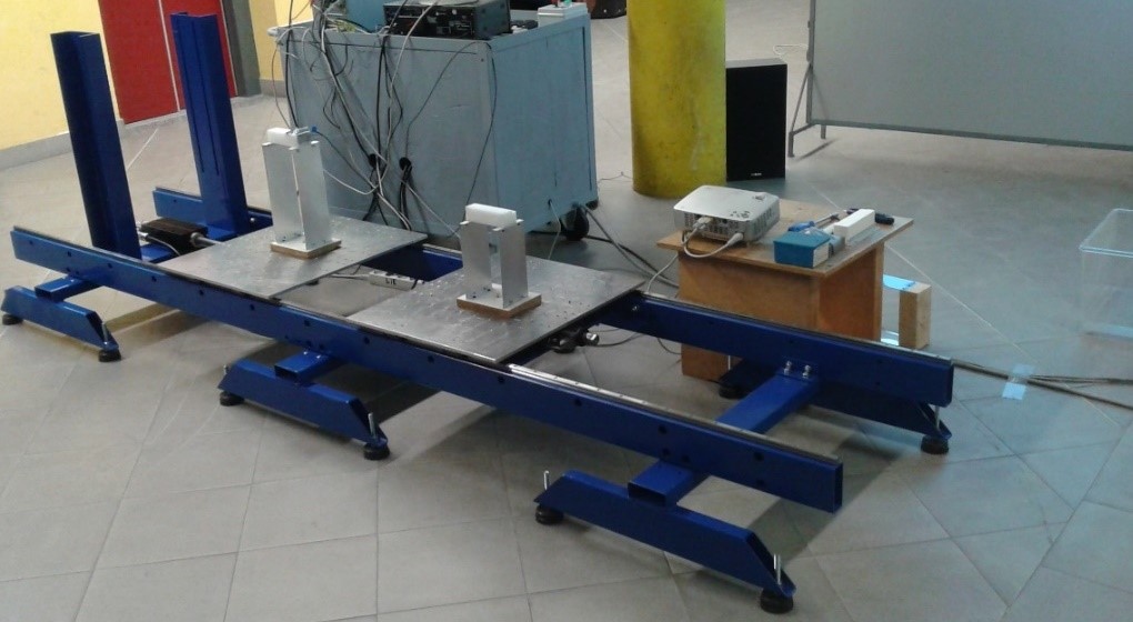
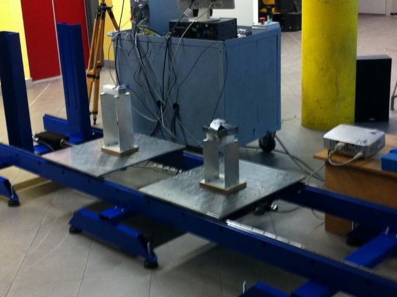
Case 1: Resonance phenomenon in SDOF models (1)In this first case, two SDOF models with same mass (m=0.21kg) on the top and same material but different height (H1=30cm and H2=20cm) were performed in the test. The mechanical characteristics of the material were unknown; therefore, the natural frequencies of each model were also unknown. However, by applying the theory of vibration, which says that the natural frequency depends on the square of the stiffness and this on the inverse of the length, it was expected to been seen first the resonance phenomenon in the highest model as its natural frequency was lower than in the smallest model. After running the first simulation, the natural frequencies of the models could be determined (f1=2.5Hz and f2=4.3Hz) by analysing at which frequency the amplitude was maximum. Once the two natural frequencies were known, the stiffness in each configuration could be evaluated (K1=51.8N/m and K2=156.72N/m).
The objective of this second case was to modify the dynamic properties of the models with the purpose of achieving two different structures with the same natural frequency. With this intention, it could be changed both the mass and the stiffness, but because of the structure was built, the most effective way to change the dynamic properties was by modifying the mass. Therefore, after doing some calculations the result showed that it was necessary to add a mass of 0.46kg in the smallest model in order to decrease the natural frequency until it was the same as in the highest model (f1=2.5Hz).
Passive seismic control devices are highly used in structures with the goal of preventing discomfort, damage or structural failure. These devices have no feedback capability between them, structural elements and the ground. Tuned Mass Dampers (TMD) are included in this type of devices and typically are huge concrete blocks or steel bodies mounted in skyscrapers or other structures, and moved in opposition to the resonance frequency oscillations of the structures by means of springs, fluid or pendulums. In this case a TMD system was studied through hanging a mass from the top of the highest structure. Adding an extra mass to the SDOF model implies to transform the system in a two degrees of freedom system with two different natural frequencies. However, the amplitude in both natural frequencies was lower than in the initial configuration as the result of vibration absorption.
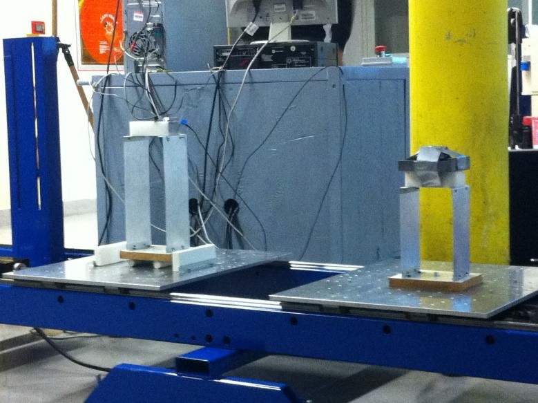
Base isolation system is one of the most powerful tools of earthquake engineering pertaining to the passive seismic control systems. It is a collection of structural elements which should substantially decouple a superstructure from its substructure resting on a shaking ground thus protecting the structure’s integrity. Hence, it involves the installation of isolators beneath every supporting point of the structure. The isolators have a much lower lateral stiffness than the structure, which allows to separate it from the ground and to not transfer seismic energy to the structure. When a base isolation system is applied to a structure, its natural period increases which decrease the spectral acceleration but increase the displacements. However, the displacements occur at the base isolator level and the structure deforms pretty much as a rigid body, also the shear forces in the base are much lower. In order to simulate a base isolation system, the structure was unattached from the table and two cylinders were put between the structure’s platform and the shaking table, also two barriers (one in each side of the structure) were fixed to the shaking table with the aim of limiting the displacements of the base.
The last case regarding to structural models consisted in testing a two-story shear frame. The goal was to visualize the different modes of vibration that has a structure depending of its degrees of freedom. In this case the structure had two degrees of freedom due that the structure is a shear type frame with two floors and the unique degree of freedom at each floor is the longitudinal displacement. Before realizing the test, the two natural frequencies of the different modes were evaluated by solving an eigenvalue problem (for more information see the "Shaking table tests" presentation) in order to compare it with the results obtained with the shaking table test. As it was expected, the shaking table test reflected the analytical simulation, seeing first (at f1=1.75Hz) the first mode of vibration in which both floors were moving to the same side and seeing in a second place with a higher frequency (f2=4.59Hz) the second mode of vibration in which each floor were moving to the opposite direction.
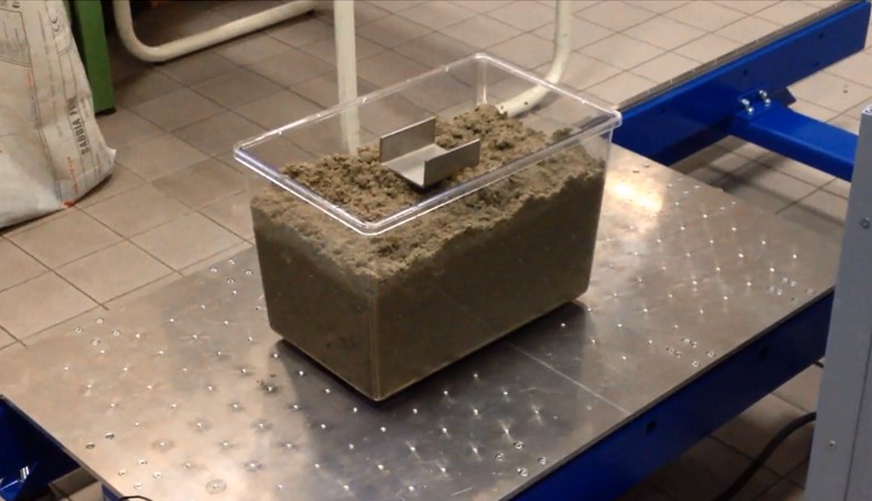
Soil liquefaction describes a phenomenon where by a saturated or partially saturated soil substantially loses strength and stiffness in response to an applied stress, usually earthquake shaking or other sudden change in stress condition, causing it to behave like a liquid. Because of this fast vibration, the soil is not able to drain so it is under undrained conditions. Hence, a sand with low density (the one it was tested) present a contract behaviour in which the water pressures increase fast causing a decreasing of the shear stress that trigger a reduction of soil resistance making it closer to collapse. Besides, because of this high water pressure in the soil some cracks are opened letting pass the water to the surface. For testing the liquefaction phenomenon, a sedimentary thin sand with low density was put in a transparent box with water until it covered all the water and it was dry sand on the surface. Besides, a little piece of metal simulating a building was put on the top in order to see the effect of liquefaction on buildings.
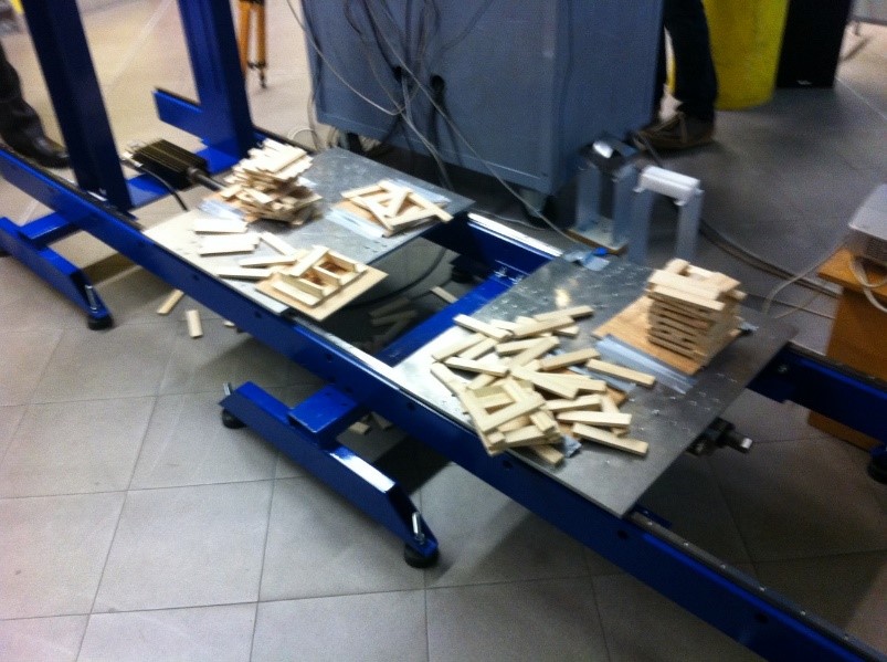
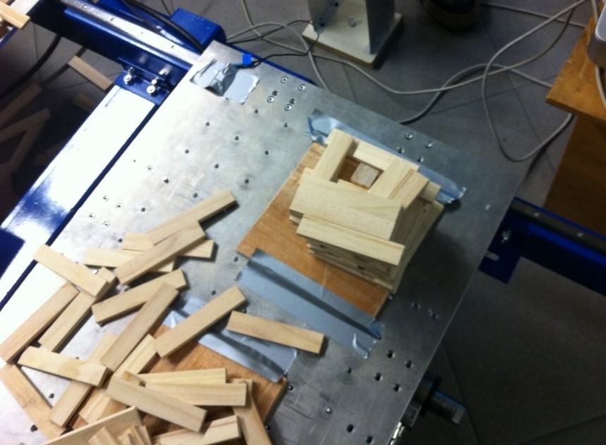
Once all the demonstrations took place, it was organized a seismic design competition for the students with the aim they could apply concepts and ideas seen at class and also take part of a shaking table test in a more active manner. For the competition, the students were divided in small groups and each one had to build a structure with small wooden blocks that were given to them. The structures were tested with a reproduction of El Centro earthquake. The structures with low stiffness collapsed immediately while the others were almost not affected. Then, with the purpose to view all the structures collapsing it was implemented a sweep. The structures did not show any affection at low frequencies, but as the frequency was increasing to high values most of the structures started to vibrate and later to collapse. This observation indicates that the structures built with small wooden blocks had a high natural frequency.